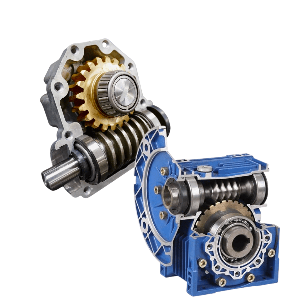
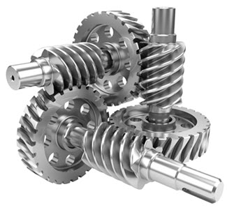
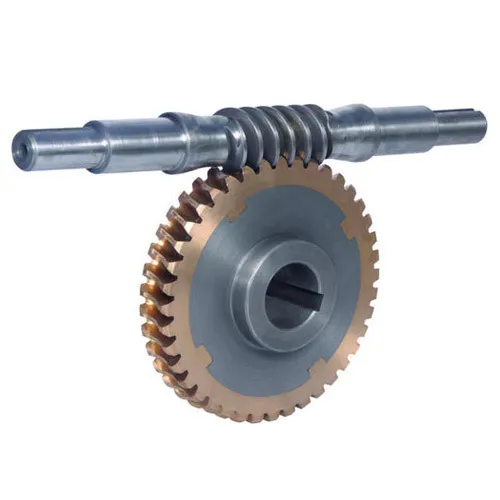
Product Description
Quick Details
Warranty:
3months-1year
Place of Origin:
ZheJiang , China
Brand Name:
lanjiu
Model Number:
110AS571-15RV63-10
Usage:
BOAT, Home Appliance
Type:
SERVO MOTOR
Torque:
57n.m
Construction:
Permanent Magnet
Commutation:
Brushless
Protect Feature:
Drip-proof
Speed(RPM):
1500rpm
Continuous Current(A):
40A
Efficiency:
Ie 3
Certification:
ce
Product Name:
BLDC Motor
Motor type:
Permanent BLDC Motor SERVO MOTOR
Name:
Brushless Servo Motor
Keywords:
High Torque Gear Motor
Application:
AGV ROBOT
Function:
CLOSE LOOP
Power:
800w 1000W 1500w
Rated Speed:
1500 Rpm
Diameter:
110MM
Packaging & Delivery
Selling Units:
Single item
Single package size:
30X15X15 cm
Single gross weight:
15.000 kg
Package Type:
Carton packaging
Picture E
high torque brushless servo motor encoder 48v 1000w 1500w brushless dc servo motor
Product Overviews
What is a Brushless DC motor (BLDC)?
A brushless DC motor (known as BLDC) is a permanent magnet synchronous electric motor which is driven by direct current (DC) electricity and it accomplisheslectronically controlled commutation system (commutation is the process of producing rotational torque in the motor by changing phase currents through it at appropriate times) instead of a mechanically commutation system. BLDC motors are also referred as trapezoidal permanent magnet motors.
It has no mechanical commutator and associated problems
High efficiency due to the use of permanent magnet rotor
High speed of operation even in loaded and unloaded conditions due to the absence of brushes that limits the speed
Smaller motor geometry and lighter in weight than both brushed type DC and induction AC motors
Long life as no inspection and maintenance is required for commutator system
Higher dynamic response due to low inertia and carrying windings in the stator
Less electromagnetic interference
Quite operation (or low noise) due to absence of brushes
|
a. High Torque to inertia ratio&up to 25000Nm/kgm² |
|
b. Fast dynamic response *time constant <20ms |
|
c. Wide speed adjusting&feedback up to 1000:1 |
|
d. Steady speed precision up to 0.5% |
|
e. High overload,2Mn/30s,3.5N.m/10s |
|
f. Small volume and light |
|
g. Silent,the lowest noise is only 45dB(A) |
|
h. Protected with IP65,Class F insulation |
Product Uses
| Model | 110BS571-15RV63-10 | |
| Volt | V | 48V |
| Power | W | 1500W |
| Rated Torque | N.m | 9.6 |
| Rated Speed | r/min | 1500 |
| Rated Current | A | 40 |
| Peak Torque | N.m | 16.6 |
| Line Resistance | Ω | 0.6 |
| Rotor Constant | mH | 0.28 |
| Torque Constant | Nm/A | 0.17 |
| Back EMF Constant | v/kr/min | 17.3 |
| Mechanical Time Constant | ms | 0.56 |
| Electrical Time Constant | ms | 0.8 |
| Encoder | ppr | 2500 |
| Weight | KG | 8 |
Brushless dc servo motor Diemsion
| Color | Red | Green | Gray | Yellow | Brown | Bule | Orange |
| Output | 5V | A | B | C | U | V | W |
| Color | Black | White/Green | White/Gray | White/Yellow | White/Brown | White/Bule | White/Orange |
| Output | 0V | A- | B- | C- | U- | V- | W- |
Encoder Infronation
| Electrical Parameter | Value |
| Output form(TTL) | Square Wave |
| Power Voltage(DV)V | 5V±5% |
| Current Consumption(mA) | <200 |
| Output Voltage VH(V) | ≥2.5 |
| Output Voltage VL(V) | ≤0.5 |
| Max Response Frequency(KHZ) | 0-350 |
| Rise/fall time(ns) | ≤200 |
| Ambient Temperature(ºC) | -30~+85 |
| Storage Temperature(ºC) | -40~+95 |
| Weight(kg) | 0.3 |
| Protection grade | IP40 |
| General Maximum Speed(rpm) | 3000 |
| Max speed(rpm) | 6000 |
| Starting Torque [N.m(25ºC)] | 5×10⁻³ |
| Inertia Moment(kg m2) | 5×10⁻⁶ |
| Shaft Max Load(N.m) | Radial Direction 10 |
| Shaft Max Load(N.m) | Axial Direction 10 |
| maximum permissible acceleration(Rad/S2) | 10000 |
high torque brushless motor with encoder 48v 1000w brushless dc servo motor
Detailed Images
Related Products
| Model | Volt | Power | Rated speed | Rated Current | Rated Torque | Peak Torque | Encoder |
| Unit | V | W | r/min | A | N.m | N.m | PPR |
| LK60BS5711-30 | 24 | 100 | 3000 | 5.4 | 0.318 | 0.95 | 2500 |
| LK60BS5712-30 | 24 | 200 | 3000 | 10.4 | 0.63 | 1.89 | 2500 |
| LK80BS5712-15 | 12 | 200 | 1500 | 22 | 1.27 | 3.8 | 2500 |
| LK80BS5712-15 | 24 | 200 | 1500 | 9.4 | 1.27 | 3.8 | 2500 |
| LK80BS0402-15 | 48 | 200 | 1500 | 4.7 | 1.27 | 3.8 | 2500 |
| LK80BS5714-15 | 12 | 400 | 1500 | 40 | 2.55 | 7.65 | 2500 |
| LK80BS5714-15 | 24 | 400 | 1500 | 21.3 | 2.55 | 7.65 | 2500 |
| LK80BS0404-15 | 48 | 400 | 1500 | 10.6 | 2.55 | 7.65 | 2500 |
| LK80BS5714-30 | 24 | 400 | 3000 | 18.8 | 1.27 | 3.8 | 2500 |
| LK80BS0404-30 | 48 | 400 | 3000 | 9.4 | 1.27 | 3.8 | 2500 |
| LK110BS5717-15 | 24 | 750 | 1500 | 44 | 4.7 | 17 | 2500 |
| LK110BS0408-15 | 48 | 800 | 1500 | 22 | 5 | 17.9 | 2500 |
| LK110BS5710-15 | 24 | 1000 | 1500 | 52 | 6.3 | 22 | 2500 |
| LK110BS571-15 | 48 | 1000 | 1500 | 28 | 6.3 | 22 | 2500 |
| LK110BS571-15 | 48 | 1500 | 1500 | 37.5 | 9.5 | 28 | 2500 |
| LK110BS0420-25 | 48 | 2000 | 2500 | 55 | 7.6 | 26 | 2500 |
| LK130BS0430-15 | 48 | 3000 | 1500 | 73 | 19 | 57 | 2500 |
|
Shipping Cost:
Estimated freight per unit. |
To be negotiated |
|---|
| Function: | Protection, Monitoring, Measurement |
|---|---|
| Condition: | New |
| Customized: | Customized |

What are the advantages and disadvantages of using a worm gear?
A worm gear offers several advantages and disadvantages that should be considered when selecting it for a specific application. Here’s a detailed explanation of the advantages and disadvantages of using a worm gear:
Advantages of using a worm gear:
- High gear reduction ratio: Worm gears are known for their high gear reduction ratios, which allow for significant speed reduction and torque multiplication. This makes them suitable for applications that require precise motion control and high torque output.
- Compact design: Worm gears have a compact design, making them space-efficient and suitable for applications where size is a constraint. The worm gear’s compactness allows for easy integration into machinery and equipment with limited space.
- Self-locking capability: One of the key advantages of a worm gear is its self-locking property. The angle of the worm thread prevents the reverse rotation of the output shaft, eliminating the need for additional braking mechanisms. This self-locking feature is beneficial for maintaining position and preventing backdriving in applications where holding the load in place is important.
- Quiet operation: Worm gears typically operate with reduced noise levels compared to other gear types. The sliding action between the worm and the worm wheel teeth results in smoother and quieter operation, making them suitable for applications where noise reduction is desired.
- High shock-load resistance: Worm gears have good shock-load resistance due to the sliding contact between the worm and the worm wheel teeth. This makes them suitable for applications that involve sudden or intermittent loads, such as lifting and hoisting equipment.
- Easy installation and maintenance: Worm gears are relatively easy to install and maintain. They often come as a compact unit, requiring minimal assembly. Lubrication maintenance is crucial for optimal performance and longevity, but it is typically straightforward and accessible.
Disadvantages of using a worm gear:
- Lower efficiency: Worm gears tend to have lower mechanical efficiency compared to some other gear types. The sliding action between the worm and the worm wheel teeth generates higher frictional losses, resulting in reduced efficiency. However, efficiency can be improved through careful design, quality manufacturing, and proper lubrication.
- Limited speed capability: Worm gears are not suitable for high-speed applications due to their sliding contact and the potential for heat generation. High speeds can lead to increased friction, wear, and reduced efficiency. However, they excel in low to moderate speed applications where high torque output is required.
- Heat generation: The sliding action between the worm and the worm wheel generates friction, which can result in heat generation. In high-load or continuous-duty applications, this heat buildup can affect the efficiency and longevity of the system. Proper lubrication and heat dissipation measures are necessary to mitigate this issue.
- Less suitable for bidirectional motion: While worm gears offer excellent self-locking capabilities in one direction, they are less efficient and less suitable for bidirectional motion. Reversing the direction of the input or output shaft can lead to increased friction, reduced efficiency, and potential damage to the gear system.
- Lower accuracy in positioning: Worm gears may have lower accuracy in positioning compared to some other gear types, such as precision gear systems. The sliding contact and inherent backlash in worm gears can introduce some degree of positioning error. However, for many applications, the accuracy provided by worm gears is sufficient.
- Potential for wear and backlash: Over time, the sliding action in worm gears can lead to wear and the development of backlash, which is the play or clearance between the worm and the worm wheel teeth. Regular inspection, maintenance, and proper lubrication are necessary to minimize wear and reduce backlash.
When considering the use of a worm gear, it’s essential to evaluate the specific requirements of the application and weigh the advantages against the disadvantages. Factors such as torque requirements, speed limitations, positional stability, space constraints, and overall system efficiency should be taken into account to determine if a worm gear is the right choice.

How do you ensure proper alignment when connecting a worm gear?
Ensuring proper alignment when connecting a worm gear is crucial for the smooth and efficient operation of the gear system. Here’s a detailed explanation of the steps involved in achieving proper alignment:
- Pre-alignment preparation: Before connecting the worm gear, it is essential to prepare the components for alignment. This includes cleaning the mating surfaces of the gear and shaft, removing any debris or contaminants, and inspecting for any signs of damage or wear that could affect the alignment process.
- Measurement and analysis: Accurate measurement and analysis of the gear and shaft alignment are essential for achieving proper alignment. This typically involves using precision alignment tools such as dial indicators, laser alignment systems, or optical alignment instruments. These tools help measure the relative positions and angles of the gear and shaft and identify any misalignment.
- Adjustment of mounting surfaces: Based on the measurement results, adjustments may be required to align the mounting surfaces of the gear and shaft. This can involve shimming or machining the mounting surfaces to achieve the desired alignment. Care should be taken to ensure that the adjustments are made evenly and symmetrically to maintain the integrity of the gear system.
- Alignment correction: Once the mounting surfaces are prepared, the gear and shaft can be connected. During this process, it is important to carefully align the gear and shaft to minimize misalignment. This can be done by observing the alignment readings and making incremental adjustments as necessary. The specific adjustment method may vary depending on the type of coupling used to connect the gear and shaft (e.g., keyway, spline, or flange coupling).
- Verification and final adjustment: After connecting the gear and shaft, it is crucial to verify the alignment once again. This involves re-measuring the alignment using the alignment tools to ensure that the desired alignment specifications have been achieved. If any deviations are detected, final adjustments can be made to fine-tune the alignment until the desired readings are obtained.
- Secure fastening: Once the proper alignment is achieved, the gear and shaft should be securely fastened using appropriate fasteners and tightening procedures. It is important to follow the manufacturer’s recommendations for torque values and tightening sequences to ensure proper clamping force and prevent any loosening or slippage.
It is worth noting that the alignment process may vary depending on the specific gear system, coupling type, and alignment tools available. Additionally, it is important to refer to the manufacturer’s guidelines and specifications for the particular gear and coupling being used, as they may provide specific instructions or requirements for alignment.
Proper alignment should not be considered a one-time task but an ongoing maintenance practice. Regular inspections and realignment checks should be performed periodically or whenever there are indications of misalignment, such as abnormal noise, vibration, or accelerated wear. By ensuring proper alignment during the initial connection and maintaining it throughout the gear’s operational life, the gear system can operate optimally, minimize wear, and extend its service life.

Are there different types of worm gears available?
Yes, there are different types of worm gears available to suit various applications and requirements. Here are some of the commonly used types:
Single Enveloping Worm Gear:
The single enveloping worm gear, also known as a cylindrical worm gear, has cylindrical teeth on the worm wheel that mesh with the helical thread of the worm. The teeth of the worm wheel wrap around the worm in a single enveloping manner. This design provides better contact and load distribution, resulting in higher load-carrying capacity and smoother operation. Single enveloping worm gears are commonly used in heavy-duty applications where high torque transmission is required.
Double Enveloping Worm Gear:
The double enveloping worm gear is a specialized type of worm gear that provides even greater load-carrying capacity compared to the single enveloping design. In a double enveloping worm gear, both the worm and the worm wheel have curved tooth profiles. The teeth of the worm wrap around the worm wheel while the teeth of the worm wheel wrap around the worm. This double enveloping action increases the contact area, improves load distribution, and enhances the gear’s efficiency. Double enveloping worm gears are used in applications that demand high torque and precision, such as aerospace and defense industries.
Non-enveloping Worm Gear:
The non-enveloping worm gear, also known as a non-throated worm gear, has a worm wheel with teeth that do not fully wrap around the worm. Instead, the worm wheel has straight or slightly curved teeth that engage with the helical thread of the worm. Non-enveloping worm gears are simpler in design and less expensive to manufacture compared to enveloping worm gears. They are commonly used in applications with moderate loads and where cost is a consideration.
Self-locking Worm Gear:
Self-locking worm gears are designed with a specific helix angle of the worm’s thread to provide a self-locking effect. This means that when the worm is not actively driving the worm wheel, the worm wheel is prevented from rotating backward and can hold its position securely. Self-locking worm gears find applications in systems where holding position or preventing backdriving is crucial, such as elevators, lifts, and certain industrial machinery.
These are just a few examples of the different types of worm gears available. The choice of worm gear type depends on factors such as the application requirements, load capacity, efficiency, and cost considerations.


editor by CX 2023-09-05